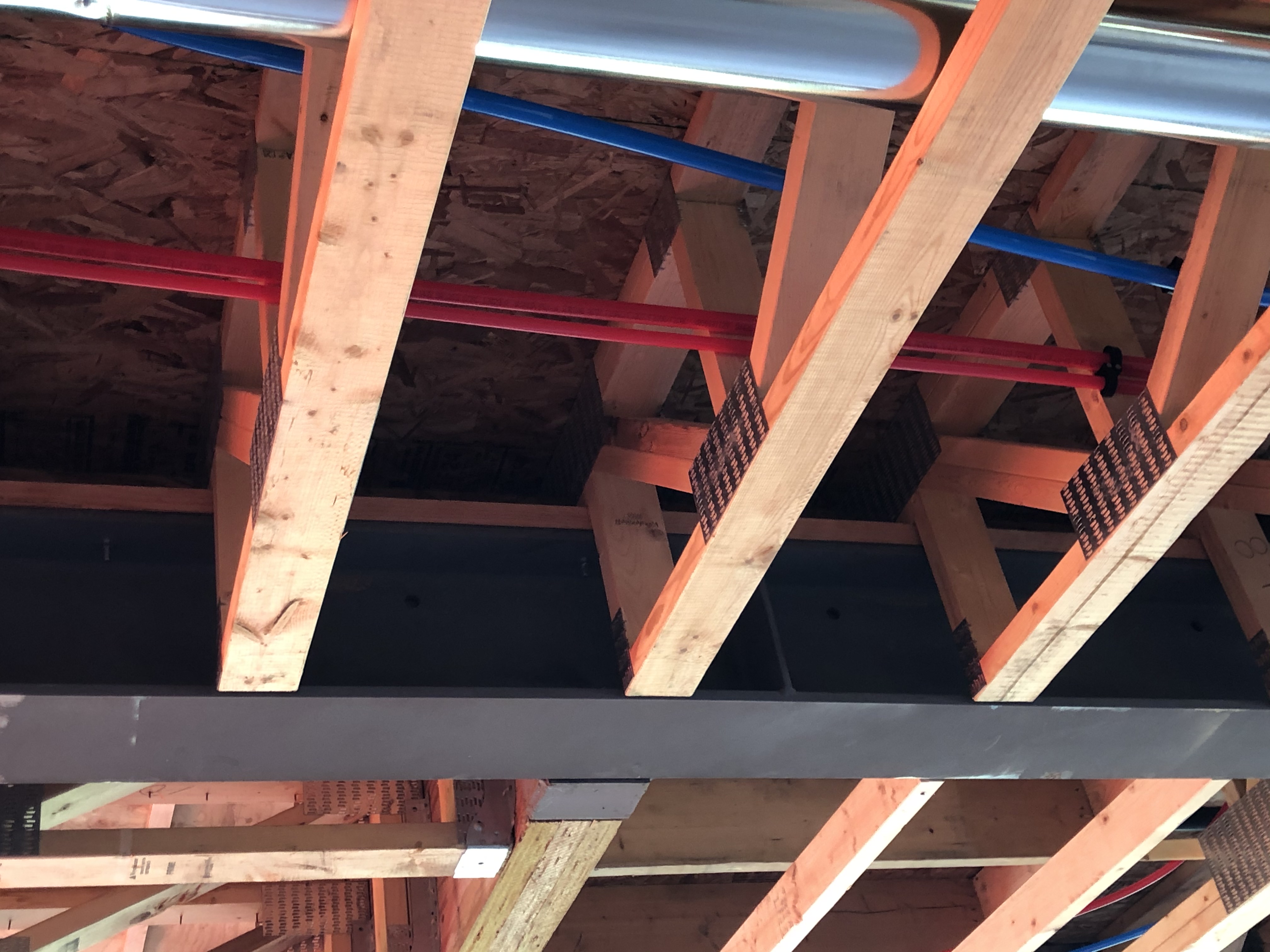
A common misunderstanding about structural engineers is that we design structures so that they don’t move. This is not entirely accurate, in fact we often design structural members to continue to perform during a certain amount of movement or deflection.

What is deflection?
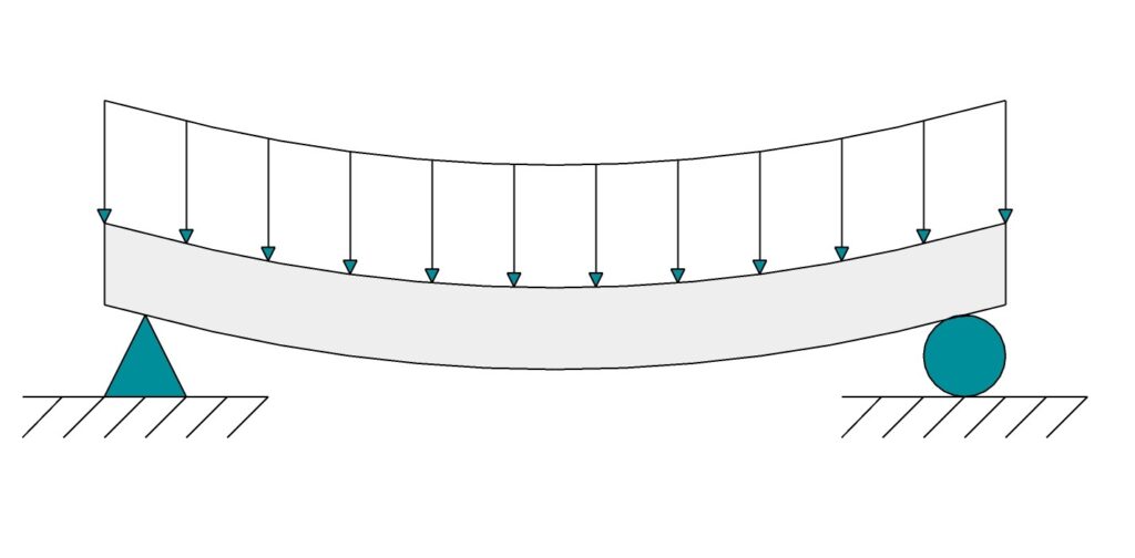
In structural engineering, deflection is the amount that a structural member moves or becomes displaced under an applied load.
Deflection is only part of the story. In accordance with the National Building Code, we consider strength, stability, fatigue, serviceability, deflection, and vibration. The intent of this article is to discuss some of the impacts of deflection in the design of beams.
How does deflection occur?

You may have seen the following equation for deflection caused by a uniformly distributed load on a simple supported beam:
Where δ is the deflection, w is the uniformly distributed load, L is the length of the span of the member, E is the modulus of elasticity, and I is the moment of inertia. E and I are material properties of the member. According to this formula, as soon as there is a load applied, including the self weight of a member, there is some amount of deflection, even if it is not visible. With an increased load, deflection increases. As the span increases, deflection increases exponentially.
How is the design load determined?

The design load is determined in accordance with Part 4 of the National Building Code. It may include the dead load (weight of building components), earthquake load and effects, lateral earth pressure load, live load due to use and occupancy, live load due to cranes, snow load, wind load, and the effects of creep, shrinkage, temperature change, and pre-stress.
How much deflection is acceptable?
The following variables must be considered:
- The intended use of the building or member – In some industrial applications, a greater amount of deflection is acceptable without impacting the space’s use. Alternatively, an area such as a testing facility or lab may have more stringent deflection criteria. Further, visible deflection is something that may make users feel uneasy.
- The potential for damage to non-structural members as a result of deflection – Rigid finishes such as drywall or tile may become cracked by excess deflection. Doors or windows may become jammed. Heat loss or moisture ingress may occur. Alternatively, non-structural members may be selected to reduce the potential for damage as a result of deflection. For example, non-rigid finishes such as vinyl flooring or vinyl wall cladding are more forgiving.
- The potential for damage to the structure itself – Too much deflection of a member can cause permanent deflection, cracking, or other structural damage. Further, too much deflection of one member may impact the structural integrity of another member that it supports, or the stability of the structure as a whole.
- Creep, shrinkage, temperature changes, and pre-stress – These are all additional factors that may impact allowable deflection.

The NBC Structural Commentary summarizes maximum deflection limits for conventional construction and applications, depending on the building component and the material type. The maximum deflection is typically calculated using the live, snow, or wind load, with some exceptions. Maximum deflections are typically specified as a ratio of the beam span. For instance, CSA S16 “Design of Steel Structures” specifies a maximum deflection for roof or floor members supporting components susceptible to cracking of 1:360. However, if it supports components not susceptible to cracking, deflection can be increased to 1:300. Conversely, if it supports masonry, then deflection must be reduced to the lesser of 1:480 or ¾”.
Live Load Reduction Factor
A live load reduction factor may be applied to the deflection criteria for a beam if the area that the beam supports (the tributary area) is sufficiently large. The idea is that if the tributary area becomes large enough, then the probability is reduced for the design live load to be applied to the full surface of tributary area. Therefore, a factor may be applied that reduces the live load relative to the size of the tributary area.
What does this all mean?
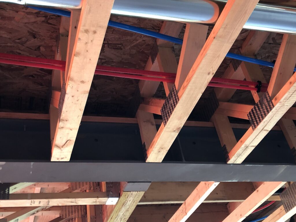
Say you are designing a 2 storey house with a second floor that extends over a 32 ft wide garage. If you have a 32 ft simply supported steel beam, criteria of 1:360 would allow for over 1” of deflection. Even if it won’t cause cracking in the drywalled ceiling or walls above, it may be visible from above or below. If you size the beam based on the deflection criteria of 1:360, you may still be able to support use of that beam selection. Consider the following:
- Does a live load reduction factor apply? In typical residential construction, a live load reduction factor is often not significant, but it may make a large enough difference in design deflection for the designer to be comfortable with beam deflection.
- What is the area above the garage being used for? For steel beam design, Part 9 of the National Building Code allows for a reduced live load of 29 psf on the second floor of a residence as compared to 40 psf on the main floor of a residence. This is because you are much less likely to experience a full live load in a bedroom or bathroom than in a living room or dining room. However, this should be use with caution: as trends such as second floor bonus rooms grow in popularity, so too might the live load experienced on the second floor of the residence.
- Are there any additional dead loads present such as a concrete topping? In this case, it may be pertinent to review deflection cause by the total load.
It is important to remember that the National Building Code is a minimum standard for building design. Professional judgement should always be used to determine if the minimum threshold is sufficient for the intended application, or if further investigation is required.

