This is Part 2 of Dampers Edition of Passive Fire Protection Systems Don’t Get The Love They Deserve. In case you missed it, here’s a link to Part 1. Here’s how the blog post is broken down:
Part 1
- NBC Installation References
- Terminology Differences: Canadian Codes vs NFPA
- Damper Basics
- Static & Dynamic Dampers
- Activation of Dampers
- Installation and Operation Instructions – Per ULC-S112
- Additional Information & Resources
- Definitions
- Referenced Standards
Part 2
- 2015 NFC ITM Requirements
- Fire Damper ITM Frequencies – NFPA 80 (2013 Edition)
- Fusible Links – ULC-S505
- Manufacturer’s Instructions – ITM Recommendations
- Access Panels
- What are some of the ITM activities for dampers?
- Nonactuated Dampers
- Actuated Dampers
- ITM Documentation
- Conclusion
- Selected ULC Standards Tests
- NBC & ULC-S505 – Fusible Links
2015 NFC ITM Requirements
The 2015 Edition of the NFC added specific requirements for the inspection, testing and maintenance of dampers. Specifically, clause (b) was added to Sentence 2.2.2.4.(5). Which now reads:
Fire dampers, smoke dampers, combination smoke/fire dampers and fire stop flaps shall be
a) inspected at intervals not greater than 12 months to ensure that they are in place and not obviously damaged or obstructed, and
b) tested in accordance with NFPA 80, “Fire Doors and Other Opening Protectives.”
The NFC now requires that dampers be visually inspected every year and tested in accordance with NFPA 80.
Fire Damper ITM Frequencies – NFPA 80 (2013 Edition)
NFPA 80 Chapter 19 outlines the requirements for the ITM of fire dampers and combination smoke/fire dampers. It is worthwhile going through all of Chapter 19, but I’ve provided a few key takeaways.
NFPA 80 requires that fire dampers to be:
- inspected and tested after installation,
- inspected and tested 1 year after installation,
- tested every 4 years thereafter, unless it is a hospital in which case every 6 years thereafter,
- inspected and tested after any repair.
Note that the tests must be conducted under conditions in which the system is intended to operate. Therefore, if the HVAC system is intended to continue operation, then the dynamic dampers must be tested with the HVAC system running.
NFPA 80 requires that in addition to the ITM requirements outlined in Chapter 19, the ITM requirements for combination smoke/fire dampers must also meet the requirements of Chapter 6 of NFPA 105. The ITM requirements are similar: same timelines, ensuring dampers operate, but the smoke detection component needs to be tested as well.
An Aside for the Inquisitive
Why are the testing requirements different for hospitals than other occupancies? This was the question posed to me. Kristin Bigda of NFPA drafted a blog post dated March 22, 2013 where she answers this very question. Check out the link here.
Fusible Links – ULC-S505
While NFPA 80 and 105 both state that the temperature rating of the fusible elements must conform to the requirements of NFPA 90A, Standard for the Installation of Air-Conditioning and Ventilating Systems, the NBC references ULC-S505, Standard for Fusible Links for Fire Protection Service.
Dampers are typically equipped with 74°C (165°F) or 100°C (212°F) fusible links.
Additional information is included at the end of the post related to the requirements of the NBC and CAN/ULC-S505.
Manufacturer’s Instructions – ITM Recommendations
Some manufacturers may have additional ITM recommendations. For example, Price Industries recommends “cycling all motorized fire and smoke dampers a minimum of once every 6 months”. It’s important to review the installation, operational and maintenance instructions for any additional ITM activities. These are best practice and important for building owners to be aware of.
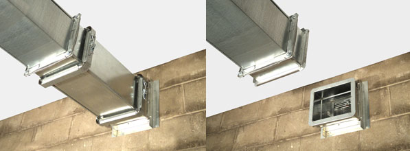
Access Panels
For dampers to be maintained, the locations need to be known and they need to be accessible. Both NFPA 80 and 105 require access panels, or removable duct sections to be installed to provide access to the damper components for ITM purposes. The access panel location should allow someone the ability to visually inspect as well as to reach the damper components and perform all the required ITM activities. This means that the access panels need to be in close proximity of the damper and of adequate size to allow a person to reach the damper and components. You may see access panels in various sizes, some of which are too small. NFPA 80 & 105 require a minimum size panel of 12”x12”. If you see smaller access panels, question the testing document. Even at 12” x 12” it may be a struggle to test some fire dampers.
NFPA 80 requires that all access panels be labelled “Fire Damper” with minimum 1” letters. While NFPA 105 requires that all access panels be labelled “Smoke Damper” with minimum ½” letters. Neither Standard specifies a requirement for combination fire/smoke damper.
What are some of the ITM activities for dampers?
Check out the AMCA Guide for Commissioning and Periodic Testing of Fire, Smoke and Other Life Safety Related Dampers, for complete information. Also, the manufacturer’s instructions will contain damper specific information.
Note that NFPA 80 requires that dynamic dampers be tested with system airflow on and to verify that the system airflow is within the velocity rating of the damper. Static fire dampers must be tested with no system airflow.
Before any testing, the damper should be inspected for anything that may impair the operation, such as damage, missing parts, rust, corrosion, obstructions, dirt dust and debris in the tracks. The damper installation should be reviewed and confirmed that it is in conformance with the listing. The damper should be cleaned and lubricated as noted in the manufacturer’s instructions.
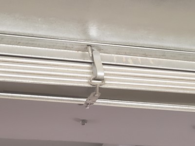
Nonactuated Dampers
To test the nonactuated damper, the fusible link need needs to be removed. The damper should fully close from the fully open position, without assistance. If the damper is equipped with a latch, the latch operation must be confirmed. The condition of the fusible link needs to be inspected to ensure that it will continue to operate as intended. If the fusible link is damaged or painted it must be replaced with one of the same size, temperature rating and load rating. Once the fusible link is installed it is important to ensure that the fire damper appears to be in operational condition and that all tools and equipment have been removed.
Actuated Dampers

For actuated dampers, a visual inspection must confirm that the damper is in the fully open position. The electrical power or air pressure is removed from the actuator. This should cause the damper to fully close. A visual inspection is required to confirm this. The damper should fully open when power or air is reapplied. The test so far only tested that the actuator functioned operating the damper. The smoke detector also needs to be inspected and tested to ensure that it functions as well.
CAN/ULC-S536-13 outlines the requirements for testing of smoke detectors. In addition to the standard testing for smoke detectors such as smoke test, sensitivity, correct installation there are additional requirements that also apply to air duct type smoke detectors. Specifically, “the positive airflow and/or sampling tube differential pressure in air duct type smoke detectors shall be tested to confirm that it is within the manufacturer’s specified limits”. The 2019 Edition of ULC-S536 provides additional details on the testing of air duct smoke detectors.
ULC-S536-2019 – 14.4.5.1. Each air duct type smoke detector shall be inspected and tested including the following as applicable:
a) Rated for the air duct size and installed correctly in the air duct system to ensure device operation;
b) The positive airflow and/or differential pressure at the sampling tubes is within the manufacturer’s specified limits for the detector; and
c) Confirm operability by introducing smoke or simulated smoke to the detector in accordance with manufacturer’s instructions.
An important note regarding testing of air duct smoke detectors in the 2019 edition of ULC-S536. Remote test switches, magnetic test points, etc. shall not be used to confirm operability (14.4.5.2).
There are dampers that are equipped with various add-ons such as position indication switches, end switches, test switches, and even wireless remote testing. These have not been discussed here.
A couple of other important notes to keep an eye out for:
- Obstructions (IT people love using existing openings to run their wires and cables.)
- Mounting screws may be incorrectly placed preventing the damper from proper operation.
- Fire caulking (follow the manufacturer’s instructions for installation.)
ITM Documentation
All ITM activities must be documented. The document should include at least the location, type of damper, date of inspection, name of inspector & company, description of damper condition, deficiencies discovered, a space to indicate when and how the deficiencies were corrected.
The NFC requires that initial verification documents be maintained for the life of the system or device. In addition, ITM documents are typically required to be maintained for a period of not less than 2 years. However, in the case of dampers, as the inspection frequency is extended, at least the current and immediately preceding documents must be maintained.
Conclusion
We know that passive fire protection systems are an important design feature to limit the spread of fire and smoke. That’s why the requirement to inspect, test and maintain them was such a valuable addition to the NFC. But dampers are out of sight and therefore out of mind. Many building owners have struggled to locate dampers, let alone determine the original HVAC design parameters. This is why it is crucial that the original design information including damper information be provided in the building fire safety plan. Dampers can’t be maintained if the owners don’t know they exist, or where they are located.
It is important to note that this blog post was based on the requirements of the NFC. The requirements in various provinces may differ. For example, the Ontario Fire Code only requires that fire dampers and fire stop flaps be inspected annually, or on an approved schedule. There is no mention of smoke dampers, or of testing the fire dampers, smoke dampers or combination smoke/fire dampers.
There is information that was not covered in this post. Several videos were included in the first post. Additional resources include the manufacturers websites, installation documents, as well as industry associations such as SMACNA, https://www.smacna.org, AMCA, www.AMCA.org.
Selected ULC Standards Tests
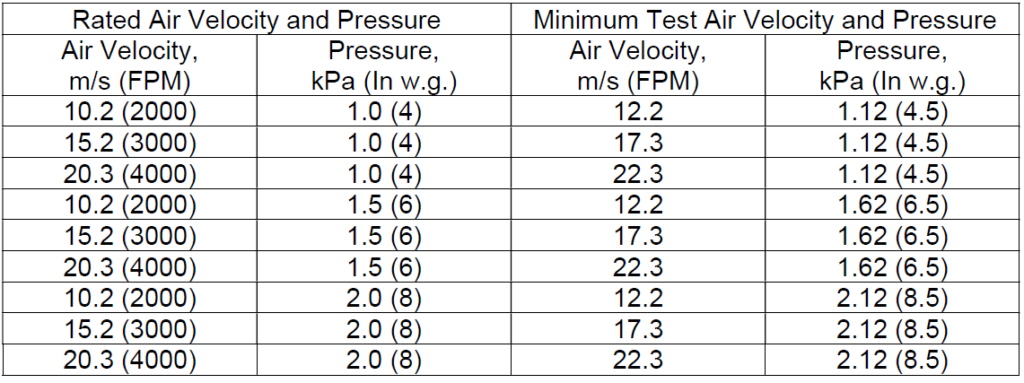
Dynamic Closure
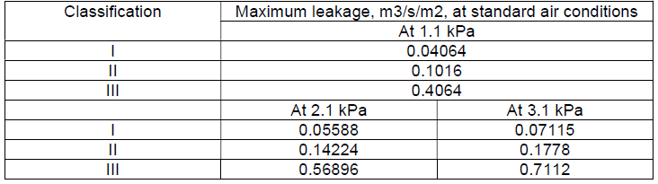
Leakage Classifications
Temperature Degradation
The damper and actuator are tested in the closed position at elevated temperatures for a duration of 30 minutes. The minimum test temperature is 121°C. After the 30-minute test while at the elevated temperature the damper is cycled, fully open & fully closed, three times. The temperature increment is increased by 55.6°C.
NBC & ULC-S505 – Fusible Links
NBC states that the temperature rating for fusible links should have a temperature rating approximately 30°C (86°F) above the maximum temperature that would exist in the system, and that the temperature rating is in conformance with ULC-S505.
Temperature Classification
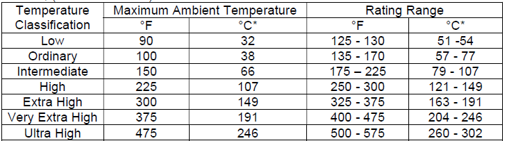
*Celsius provided for ease of use, not provided in the Table.
Minimum & Maximum Temperature Rating of Heat Responsive Devices for Static and Dynamic Dampers
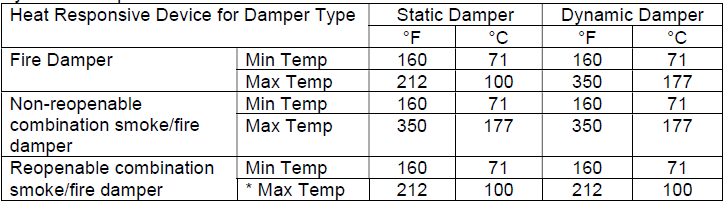
It is important to confirm the temperature rating of the heat responsive device as an improper rating may result in delay of activation, or inadvertent activation of the damper.
Definitions
Fire Damper
NFC – Means a closure consisting of a damper that is installed in a air distribution system or a wall or floor assembly and that is normally held open but designed to close automatically in the event of a fire in order to maintain the integrity of the fire separation.
ULC-S112 – A device, installed in an air distribution system, designed to close automatically upon detection of heat, to interrupt migratory airflow, and to restrict the passage of flame.
NFPA 80 – A device installed in an air distribution system, designed to close automatically upon detection of heat, to interrupt migratory airflow and to restrict the passage of flame. Fire dampers are classified for use in either static systems or for dynamic systems, where the dampers are rated for closure under airflow.
Smoke Damper
NFC – Not defined by the NFC or NBC.
ULC-S112.1 – A device within an air-distribution system to control the movement of smoke.
NFPA 80 – A device within an air distribution system to control the movement of smoke.
Combination Dampers
NFC (Combination smoke/fire damper) – is not defined by the NFC or NBC.
ULC-S112.1 (Combination fire/smoke damper) – A damper which meets the requirements of CAN/ULC-S112 and CAN/ULC-S112.1
NFPA 80 (Combination fire/smoke damper) – A device that meets both the fire damper and smoke damper requirements.
Ceiling Dampers
NFC (Fire stop flap) – means a device intended for use in horizontal assemblies required to have a fire resistance rating and incorporating protective ceiling membranes that operates to close off a duct opening through the membrane in the event of a fire.
NFPA 80 (Ceiling radiation damper) – A listed device installed in a ceiling membrane of a fire resistance-rated floor-ceiling or roof-ceiling assembly to automatically limit the radiative heat transfer through an air inlet/outlet opening.
Dynamic System (NFPA 80) – An HVAC system designed to maintain the movement of air within the system at the indication of fire.
Static System (NFPA 80) – An HVAC system designed to stop the movement of air within the system at the indication of a fire.
Qualified person (NFPA 80-2013, 3.3.95) – a person who, by possession of a recognized degree, certificate, professional standing, or skill, and who, by knowledge, training, and experience, has demonstrated the ability to deal with the subject matter, the work, or the project.
Referenced Standards
- National Building Code of Canada – 2015 Edition
- National Fire Code of Canada – 2015 Edition
- NFPA 80 – 2013 Edition
- NFPA 105 – 2013 Edition
- ULC-S112 – 2010 Edition
- ULC-S112.1 – 2010 Edition
- ULC-S112.2 Fire Stop Flaps – 2007 Edition
- ULC-S505 – 1974 Edition

2 Responses
Appreciate the ‘Aside for the Inquisitive’. 😀 Great post Jim!