Passive fire protection systems are an integral component of the overall fire safety systems in a building. And yet they are often forgotten about and not maintained. Where is the love? These systems are not set it and forget it systems. They require ongoing inspection, testing and maintenance too!
Why is this blog post important?
The 2015 Edition of the National Fire Code of Canada (NFC) added a requirement to test fire dampers, smoke dampers, combination smoke/fire dampers and fire stop flaps in accordance with NFPA 80 (2013 Edition), “Fire Doors and Other Opening Protectives”.
This blog post does not cover the requirements of NFPA 92, Standard for Smoke Control Systems.

(courtesy of Shoemaker Manufacturing Company)
Overview
This blog post is intended to provide some basic background information on dampers as well as an overview of the inspection, testing and maintenance (ITM) requirements for:
- fire dampers,
- smoke dampers,
- combination smoke/fire dampers, and
- fire stop flaps.
Note: For the remainder of this post when referring to all the above, the general term damper is used. Where there are specific requirements related to individual type of damper, the specific term is used.
This blog post is split into two separate parts (this is Part 1, and Part 2 can be found HERE). This post is also broken down into several smaller sections for easy navigation.
The 2015 Edition of the National Fire Code of Canada (NFC) added a requirement to test fire dampers, smoke dampers, combination smoke/fire dampers and fire stop flaps in accordance with NFPA 80 (2013 Edition), “Fire Doors and Other Opening Protectives”.
(courtesy of Greenheck)
Part 1
- NBC Installation References
- Terminology Differences: Canadian Codes vs NFPA
- Damper Basics
- Static & Dynamic Dampers
- Activation of Dampers
- Installation and Operation Instructions – Per ULC-S112
- Additional Information & Resources
- Definitions
- Referenced Standards
Part 2
- 2015 NFC ITM Requirements
- Fire Damper ITM Frequencies – NFPA 80 (2013 Edition)
- Fusible Links – ULC-S505
- Manufacturer’s Instructions – ITM Recommendations
- Access Panels
- What are some of the ITM activities for dampers?
- Nonactuated Dampers
- Actuated Dampers
- ITM Documentation
- Conclusion
- Selected ULC Standards Tests
- NBC & ULC-S505 – Fusible Links
NBC Installation References
This is a quick summary of damper installation references from the 2015 Edition of the National Building Code of Canada (NBC). The NBC requires that fire dampers be installed in accordance with NFPA 80. And that smoke dampers and combination smoke/fire dampers be installed in conformance with NFPA 105, Standard for Smoke Door Assemblies and Other Opening Protectives. In addition, dampers are required to conform to the following ULC Standards.
- CAN/ULC-S112, Fire Test of Fire Damper Assemblies,
- CAN/ULC-S112.1 Leakage Rated Dampers for Use in Smoke Control Systems
- CAN/ULC-S112.2 Fire Test of Ceiling Firestop Flap Assemblies
Terminology Differences: Canadian Codes vs NFPA
(courtesy of Nailor Industries Inc.)
Prior to jumping into the details, it is important to note that there are differences in the terminology between the Canadian Codes and the NFPA Standards. You may have noticed “combination smoke/fire damper” and “fire stop flap”. The Canadian Codes refer to combined fire damper and smoke damper as a “combination smoke/fire damper”. Whereas NFPA 80 and 105 refer to them as combination fire/smoke damper”. It is important to note that the term fire damper is italicized, meaning it is a defined term in the Canadian Codes. Note that the Canadian Codes do not define smoke damper. As such, the words smoke, and fire have been interchanged to allow the defined term, ‘fire damper’ to remain intact; at least that’s my opinion. In addition, the Canadian Codes refer to “fire stop flap”. While NFPA uses the term ceiling radiation dampers. I don’t have any idea where the term fire stop flap came from, so I did a google search. I found NRC Building Research Note, 1980-01 which states, “A ‘fire stop flap’ or ‘ceiling damper’ …”. Clearly the term ceiling damper was around back then too. If you know where the term fire stop flap came from and why we chose to use it rather than ceiling radiation damper, please let me know as I’m curious.
Various definitions from the NBC, ULC Standards and NFPA are provided at the end of this post.
You can have a read of NRC Publication Archives – Fire tests to assess effects of large duct openings on fire resistance of
steel-supported floor-ceiling assemblies for additional info.
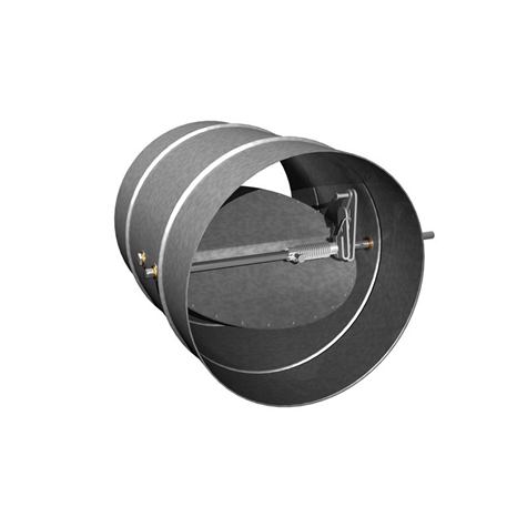
Damper Basics
(courtesy of Ruskin)
Dampers are an integral component of compartmentation. Compartmentation is one of the seven principles of life safety. If you don’t know what the seven principles of life safety are, check out my previous blog post where I break them down.
It is important to note that there are various parameters for dampers, including rating of the heat responsive device, classification, mounting details, etc. This is a brief overview for discussion. Maybe a future blog post will outline the requirements of dampers from the building design and installation perspective.
Fire dampers and combination smoke/fire dampers are typically installed within (or adjacent to) a fire rated assembly that is required to have a fire-resistance rating. Fire dampers, smoke dampers and combination smoke/fire dampers are installed either horizontally or vertically. While fire stop flaps are only installed horizontally in the listed fire rated assembly. Dampers are intended to activate either by heat, and/or smoke. The fire resistance rating of the assembly in which the damper is located is maintained by the activation of the damper. Most often you will see a 1.5 hour fire protection rating. It is important to note that smoke dampers and combination smoke/fire dampers are also required to provide additional ratings such as temperature degradation and leakage ratings. Additional information on these additional tests is provided at the end of the 2nd post.
Dampers are an integral component of compartmentation. Compartmentation is one of the seven principles of life safety. If you don’t know what the seven principles of life safety are, check out my previous blog post where I break them down.
Static & Dynamic Dampers
(courtesy of Price Industries)
There are two classifications of dampers: static and dynamic. Static dampers are used in systems were the HVAC system shuts down in the event of a fire or for air transfer openings in walls. Dynamic dampers are installed in HVAC systems where the system may continue to operate during a fire. As such, dynamic dampers are equipped with actuators or springs to close under the pressure of moving air. These dampers are provided with rated air velocities (m/s) and closure pressure (kPa) ratings. Additional information on these other ratings is provided at the end of the 2nd post.
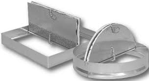
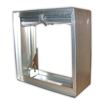
Dampers come in various types of construction: curtain blade, multi-blade and round (shown on the right). You will also see several variations such as Type A, Type B and Type C dampers with sleeves and no sleeves. Additional information on the various terms are provided in the Additional Resources and Information section.
[convertkit form=1987179]
Activation of Dampers
(courtesy of Ruskin)
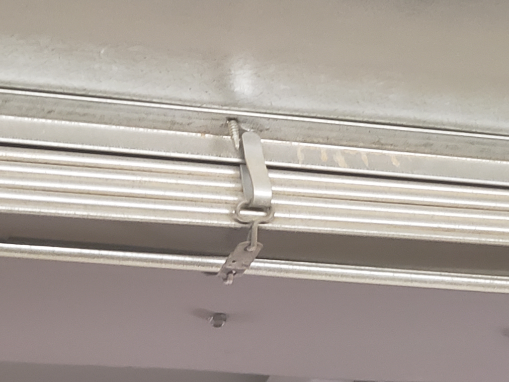
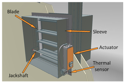
Nonactuated fire dampers and fire stop flaps operate via a fusible link. These dampers may close by gravity or by spring.
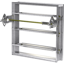
Actuated dampers are equipped with an electronic or pneumatic actuator. The actuator is typically mounted on the jackshaft. The actuator rotates the jackshaft closing the blades of the damper.
Actuated fire dampers are equipped with a heat responsive device, noted in the drawings as “thermal sensor”. While combination smoke/fire dampers are equipped with a heat responsive device and smoke detection. Electrical power or air is supplied to the actuator keeping the damper in the open position. Activation of the smoke detector or heat responsive device cuts off power, or air pressure to the actuator causing the damper to close. Actuated fire dampers and combination smoke/fire dampers are installed fail-safe (closed) to ensure the integrity of the fire separation is maintained.
Installation and Operation Instructions – Per ULC-S112
ULC-S112 Section 14 outlines the installation and operating instructions. (Note that ULC-S112.1 also has similar requirements with some variations which are not provided here). The most notable requirement, in both standards is that a copy of the installation and operating instructions are required to be provided in each shipping container.
The instructions are required to specify all of the following:
- The type of wall or partition (masonry or gypsum wallboard) or floor, as applicable.
- The clearances required for expansion of the fire damper, as applicable.
- The type and thickness of the sleeve material when the sleeve is field assembled.
- The type and size of fasteners and the spacing of the fasteners used in attaching the fire damper frame to the sleeve (when a sleeve is to be used and is to be field supplied), and perimeter mounting angles to the fire damper frame or the sleeve.
- The specified means of sealing the damper to ductwork or damper frame, or both, if applicable.
- The length of the sleeve or frame extending beyond the wall or floor opening.
- The type of material, size, thickness, and minimum wall/floor overlap of the perimeter mounting angles, and whether or not they are to be welded (or fastened using other means) to each other at the corners.
- That the connecting ducts shall not be continuous, and shall terminate at the sleeve or frame.
- The type of duct-sleeve connections (see Figure 1 and Section 12, Duct Impact Test) when sleeve thickness less than 1.6 mm steel is used.
- Information on connecting the actuator to the power (electric or pneumatic) supply.
- Any other specific features required for the installation and operation.
For multiple assembly of the dampers, the instructions shall also specify:
- The method of attaching individual sections together.
- When any mullions are required, their materials, sizes, locations, and the method of attaching them to the dampers.
- The maximum size of the multiple assembly that may be assembled.
- The maximum size of the individual sections that may be attached together.
A copy of the installation and operation instructions should be included in the buildings fire safety plan for each type of damper, along with the initial testing and acceptance documentation. The owner should have documentation including at least the following: location of the damper, model number, date of installation, hourly rating, mounting position, size, leakage rating, maximum velocity, maximum pressure, actuator type, power source, status switch, sleeve construction, access/equipment requirements, any additional notes. This documentation provides information for the ongoing ITM requirements, damper replacement, or building renovation.
Read more:
Giving Dampers the Love they Deserve: Part 2
Additional Information & Resources
Type A, Type B & Type C Dampers
Damper Sleeves
Ceiling Radiation Damper
Combination Fire/Smoke Damper Installation
Definitions
Fire Damper
NFC – Means a closure consisting of a damper that is installed in a air distribution system or a wall or floor assembly and that is normally held open but designed to close automatically in the event of a fire in order to maintain the integrity of the fire separation.
ULC-S112 – A device, installed in an air distribution system, designed to close automatically upon detection of heat, to interrupt migratory airflow, and to restrict the passage of flame.
NFPA 80 – A device installed in an air distribution system, designed to close automatically upon detection of heat, to interrupt migratory airflow and to restrict the passage of flame. Fire dampers are classified for use in either static systems or for dynamic systems, where the dampers are rated for closure under airflow.
Smoke Damper
NFC – Not defined by the NFC or NBC.
ULC-S112.1 – A device within an air-distribution system to control the movement of smoke.
NFPA 80 – A device within an air distribution system to control the movement of smoke.
Combination Dampers
NFC (Combination smoke/fire damper) – is not defined by the NFC or NBC.
ULC-S112.1 (Combination fire/smoke damper) – A damper which meets the requirements of CAN/ULC-S112 and CAN/ULC-S112.1
NFPA 80 (Combination fire/smoke damper) – A device that meets both the fire damper and smoke damper requirements.
Ceiling Dampers
NFC (Fire stop flap) – means a device intended for use in horizontal assemblies required to have a fire resistance rating and incorporating protective ceiling membranes that operates to close off a duct opening through the membrane in the event of a fire.
NFPA 80 (Ceiling radiation damper) – A listed device installed in a ceiling membrane of a fire resistance-rated floor-ceiling or roof-ceiling assembly to automatically limit the radiative heat transfer through an air inlet/outlet opening.
Dynamic System (NFPA 80) – An HVAC system designed to maintain the movement of air within the system at the indication of fire.
Static System (NFPA 80) – An HVAC system designed to stop the movement of air within the system at the indication of a fire.
Qualified person (NFPA 80-2013, 3.3.95) – a person who, by possession of a recognized degree, certificate, professional standing, or skill, and who, by knowledge, training, and experience, has demonstrated the ability to deal with the subject matter, the work, or the project.
Referenced Standards
- National Building Code of Canada – 2015 Edition
- National Fire Code of Canada – 2015 Edition
- NFPA 80 – 2013 Edition
- NFPA 105 – 2013 Edition
- ULC-S112 – 2010 Edition
- ULC-S112.1 – 2010 Edition
- ULC-S112.2 Fire Stop Flaps – 2007 Edition
- ULC-S505 – 1974 Edition

One Response